Trace: » electrical_design
Electrical Design
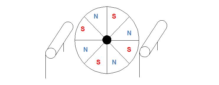
The PIC16F818 microcontroller will be used to control the stepper motor, acquire data, and send it to a laptop via a serial interface. The stepper motor has a permanent magnetic core, which is arranged in alternating north-south “pie slices”. The picture below shows what this core looked like, along with the two coils which rotate it. When a current is applied the magnets will be attracted to the coil, depending on the direction of the current. By altering these currents in a specific fashion, it is possible to get the motor to rotate in discreet steps.
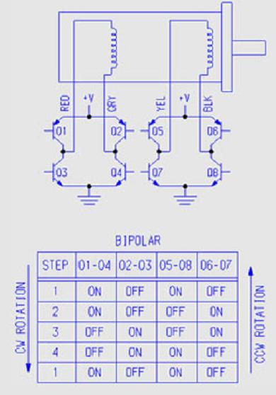
The stepper motor chosen is 42M100B1B. The wiring diagram from its data sheet is shown below.
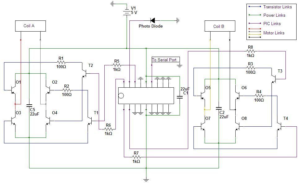
The transistors in the above diagram are operated as a switch: when the base is saturated, it makes a path across the collector-emitter junction, and when it isn’t, this path is closed. The resistance of the stepper motor is 16.7Ω. With 5V supplied each coil draws 0.3A of current. A power transistor must be used in order to avoid damage to the equipment. The output of the micro controller is not enough to saturate the power transistors, and so a second set of regular transistors will be used to amplify the microcontroller output and saturate the power transistors. One regular transistor will be used to saturate transistors 01 and 04, a second one to saturate transistor 02 and 03, a third one to saturate transistors 05 and 08, and a fourth one to saturate transistors 06 and 07.
Figure 1: Microcontroller and Stepper Motor Circuit
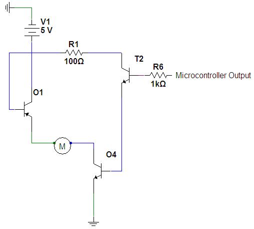
The resistor values R1, R2, R3 and R4 are chosen to be 100Ω. Figure 4 shows one part of the circuit, which would indicate current going across one of the coils in the positive direction. The voltage drop across the emitter-base junction of O1 is roughly 0.7V. The voltage drop across the resistor R1 is going to be labeled x. The voltage drop across the emitter base junction of O4 is also roughly 0.7V. The voltage drop across the emitter collector of T2 is roughly 0.1V. Performing Kirchhoff’s summation across this loop:
5V - 0.7V - x - 0.7V - 0.1V = 0 x = 3.5 V
To fully saturate a transistor to operate as a switch the current gain from the base to the emitter-collector current must be much lower than the actual gain of the transistor. The usual gain of the power transistor is 50-250.
Figure 2: Part of the Circuit
A resistor value of 100Ω will lead to a current across this loop of I = V/R = 3.5/100=0.035A. It wa mentioned earlier that the current going through the motor will be 0.3A. This means the transistor gain is g = 0.3/0.35 = 8.57. This is far below the gain of the transistor, and so the positive 5V will fully saturate the transistor.
Consider now the loop from the microcontroller output of 5V to ground. The voltage drop across the resistor R6 is x. The voltage drop across the base-emitter junction of T2 is roughly 0.6V. The voltage drop across the base-emitter junction of O4 is roughly 0.7V. Therefore, the Kirchhoff’s rule will give: 5V - x -0.6 - 0.7 = 0 x = 3.7V
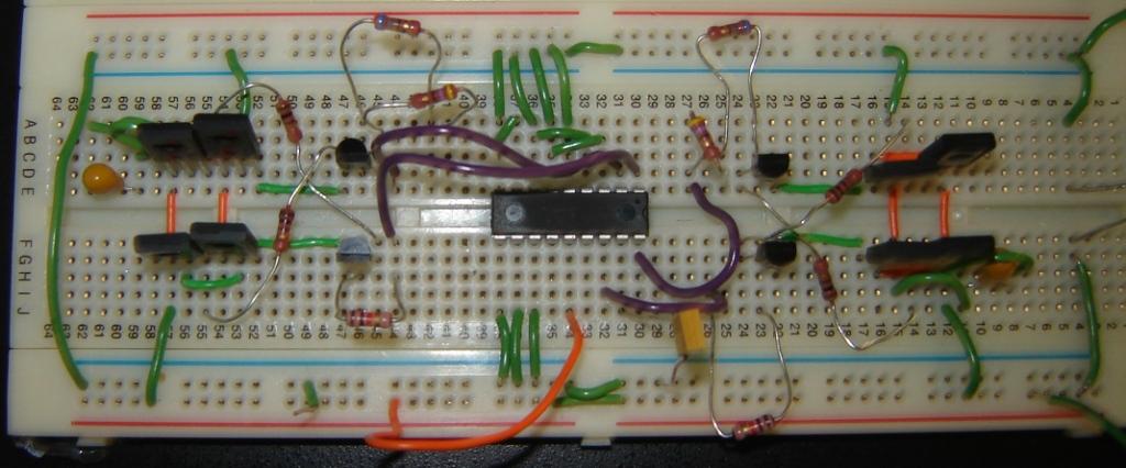
Once again, the objective in choosing the resistor value is to make the gain of the transistor lower than it actually is. The gain of the T2 transistor is between 60 and 300 [3]. Suppose the resistor value is chosen as 1kΩ. The current coming into the base of the transistor is then I=V/R = 3.7/1000 = 0.0037A. The current going through the collector-emitter junction was calculated previously to be 0.035A. Therefore the gain is g = 0.035/0.0037 = 9.46. This is once again lower than the gain of the transistor, and so the transistor will be fully saturated by the output of the microcontroller. This justifies the choice of R1 = 100Ω and R6 = 1kΩ. The same analysis applies to all the other parts of the circuit. The finished version of the circuit is shown in Figure 11. Note that in this figure some resistors are placed in pairs. This is done to achieve the desired 1kΩ by combining two smaller values.
finished version of the circuit is shown in the figure below. Note that in this figure some resistors are placed in pairs. This is done to achieve the desired 1kΩ by combining two smaller values.
You are here: start » group2 » electrical_design
