Trace: » group1start » group3weekly
This is an old revision of the document!
Weekly Reports
Week 2: Sept 9-12
This week so far our group has decided on our preferred projects for the course as well as considered some of optics involved. Presently our group's first choice of project is the traffic monitoring system, with the free-space optical communication device as a second choice. We have also decided to use, at least as a testbed, a visible red laser pointer as a source and basic phototransistors as receivers. Examining the parts catalogs has shown that these components will be feasible in terms of cost and we intend to put in an order in lab next week unless there in a change in plans.
The general design for the traffic monitoring system at this point is to have two lasers on one side of the road, and two detectors on the other side. When a vehicle or pedestrian goes by a laser beam, the beam will not reach the detector. By having two sets of lasers and detectors, we can deduce the speed of the person/vehicle based on when each laser is blocked. We can deduce if it is a person or vehicle based on whether or not both lasers are ever blocked simultaneously. Another approach to this problem is that by using the speed solved for in the first portion, we can integrate the speed over the amount of time that any single laser was blocked for to find the length of the object. This assumes no acceleration, but with the recievers placed close together, unless there are very high accelerations, this method will work well. From this, we can also tell if it was a car or person based on length of object. It will also allow our detectors to be closer together so that we require less wire. Our group discussed the possibility of minimizing the cost of the system by incorporating just one laser and one detector, and splitting the beam into two different intensities, sending them across the road at 2 different places using mirrors, and recombining them at the detector. The issue we had was that this was inherently unstable, with small changes in the positions of the mirrors misaligning the paths to the detector. In order to compensate for wind and seismic vibrations, our group discussed the idea of using a already secure object to mount our laser and receiver on. By mounting on something like a tree, or another solid object, we can ensure greater stability of the laser and also save money on building a stand that would require a large base.
Week 4: September 22-25
After the presentations of last week, our group has been assigned to the free-space optics project. We have decided to use many of our ideas from the traffic-control project and adapt them to the free-space optical system. A basic parts list including a microcontroller and phototransistor sensors was drawn up. We have decided to use a red visible wavelength, and first tests will be conducted using the lenses supplied in the lab and purchased basic laser pointers. We have decided on the use of either OOK (on-off keying) or FSK (frequency shift keying) for data encoding, and have chosen serial interface using the UART protocol for communicating with the computer. We may need to purchase a UART modem at a later date, but we have selected a microcontroller with an ADC, DAC, and UART interface in an attempt to keep our options open.
Week 5: September 29 - October 3
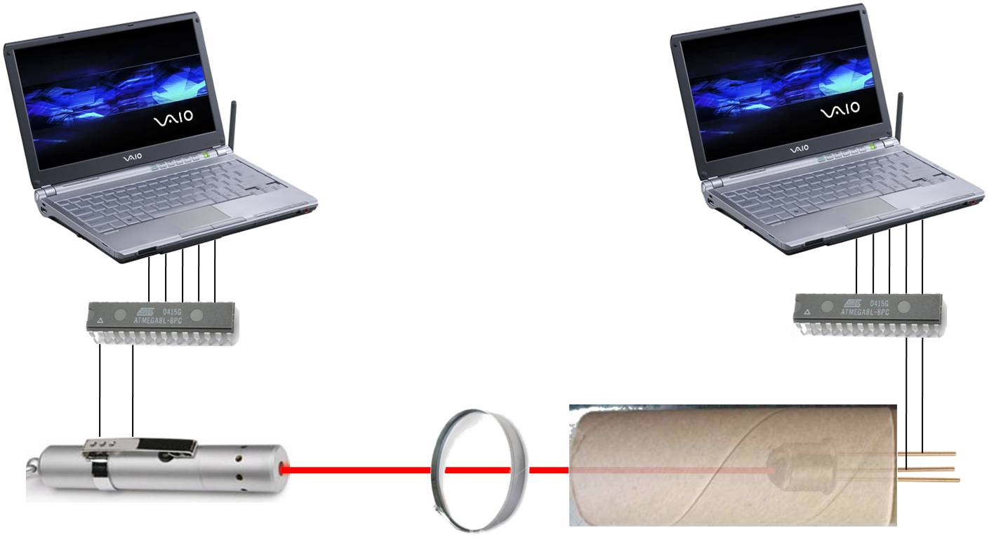
A final design was chosen for our project, as well as the required proof of concepts. The design is to use a microcontroller connected to a PC to code a photo or text into binary, and use the OOK signal to modulate the laser. A phototransistor on the other end is used to receive the signal, and a second microcontroller is used to reverse the operation, decoding the binary, and representing the text or image on the PC screen.
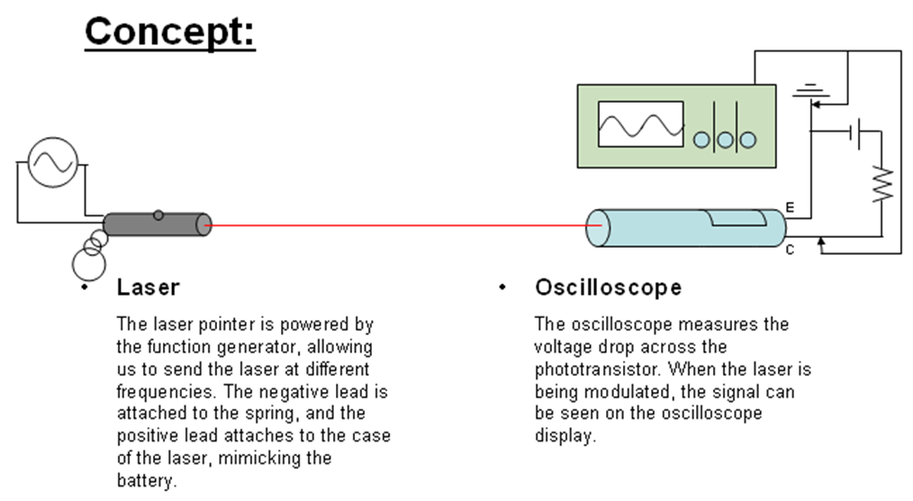
To test laser detection, we would hook the phototransistor to an oscilloscope to test the voltage the laser provides to the transistor at different distances and angles. To test the laser modulation, we would hook the laser to a function generator and the phototransistor across the room to an oscilloscope, and see if the oscilloscope is able to generate a matching wave pattern for varying frequencies (i.e. determine the highest frequency with which we can send data).
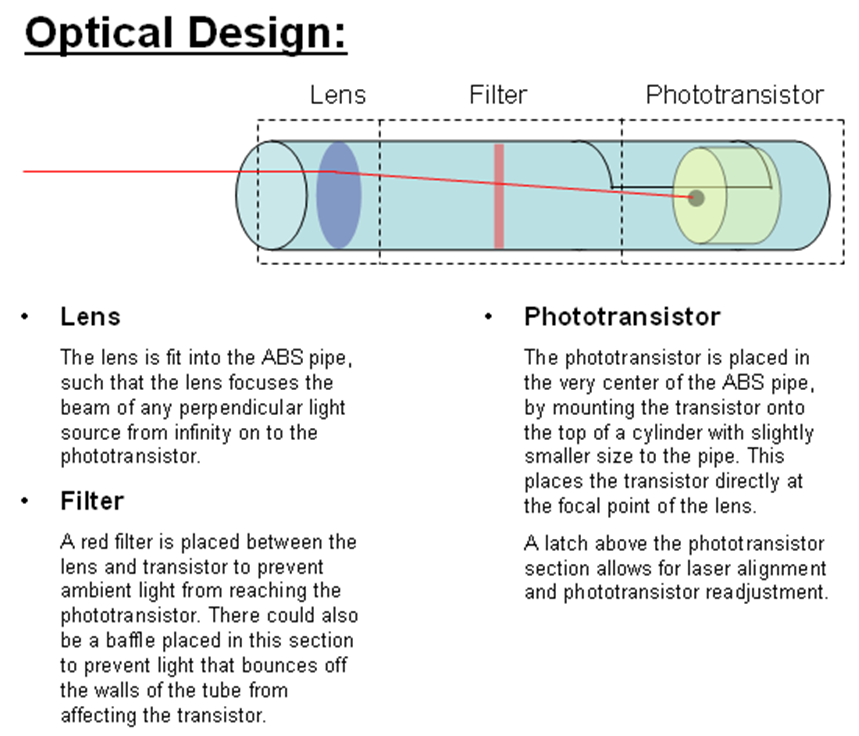
The phototransistor was chosen to be one that simulates the human eye's spectrum of absorption, so that a typical red laser could be used. This will potentially require a lot of shielding, or even filtering, at the phototransistor to prevent ambient light from providing a voltage. The microcontrollers were chosen based on the requirements to support C programming, and being able to modulate a signal at a fast enough speed. Unfortunately, the microcontroller was not of a typical type, so there are no matching programming boards to match it.
Further discussion with Glen Leinweber, lab technician, found that the microcontroller would be too slow to react at the required transmission speeds. Some further thinking is required here.
Our group has scheduled a meeting with Prof. Hranilovic for next Friday to provide some insight on free-space optics design.
Below is our design concept:
Week 7: October 13-18
The group discovered that the microcontroller we ordered is a surface mount! This means it has no leads and cannot be easily mounted on a circuit board. A new PIC microcontroller has been ordered from Microchip as a free sample, paying attention to packaging and making sure it is compatible with our programming software.
Electronic design has been further thought out. The transmit electronics will consist of a single MOSFET transistor, gated by the signal from the computer, and biased at 5 volts to drive the transmitting laser. The receive electronics will incorporate a comparator - either the PIC unit's onboard comparator or a separate one - to decode the signal by comparing it agaisnt a reference level. The reference level may be determined from the signal itself or it may be given by a second phototransistor used to sense the ambient light in the receive area.
A receiver unit has been constructed from ABS pipe. The receiver incorporates a dollar-store magnifying glass as a lens, mounted at one end of the pipe. The phototransistor sensor is mounted in one end of the pipe, at roughly the focal point of the lens. Alignment of the transmitting laser is accomplished manually, and has been proven through tests to be reasonably simple. See the design schematic for more details.
Preliminary tests show that the phototransistor outputs a modulated voltage corresponding to the modulated laser at up to the 115 kHz maximum of serial RS232 communication, but a cleaner square-wave signal is obtained at lower frequencies (~50 kHz). The photransistor may be replaced by a free-sample model ordered from TAOS if we find the signal is unusable with a comparator.
Below is our proof of concept test:
Week 7: October 13-18 At the start of this week, the group met to work on the electronic proof of principle test. A productive experiment was completed in which a comparator circuit was designed which can work directly with the output signal of the phototransistor to create a digital output. The waveform produced was suitable to be read by an RS 232 connector. There was noise however near the flip flops which was the result of the lack of a schmit trigger to prevent noise from giving the comparaor a mixed imput.
Later in the week, the group completed the proof of principle sucessuflly. The laser driver circuit was a simple n channel mosfet which takes in a signal from an RS232 or function generator to drive the transistor to allow a seperate power supply to power the laser diode. The reciever circuit is a comparator with a schmit trigger to eliminate noise while not in operation. The circuit operates at 115kilobaud maximum because that it the speed of an Rs232 connector. The output of the comparator goes into the rs232 cable. The group also considered the availablity of software which may not be able to have one way communication. It may be that two way communication will be required. Further investigation into available software must be performed.
You are here: start » group3 » group3weekly


